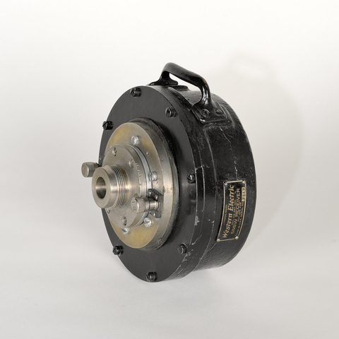
Haut-parleur
Fiche détaillée
Type de l'appareil
moteur électrodynamique de compression pour haut-parleur Western Electric WE 15A type Vitaphone ; membrane diaphrame en duralumin ; bobinage fixé à la membrane
Auteurs
Thuras Albert L.
New York, New York
Fabricants
Western Electric
New York, New York
Electrical Research Products Incorporated
New York, New York, 250 West 57th Street
Utilisateurs
Thuras Albert L.
New York, New York
Distributeurs
Western Electric
New York, N. Y., 250 West 57th Street
Sujet du modèle
Informations non disponibles
Objectif
Informations non disponibles
Taille de l'objet
Ouvert :
Informations non disponibles
Fermé :
Longueur : 11 cm
Largeur : 18.5 cm
Hauteur : 18 cm
Diamètre :
Informations non disponibles
Taille de la boîte de transport
Informations non disponibles
Remarques
Etiquette "Trade Mark Western Electric Reg. US. Pat. Off. 555 W. Receiver Pat. App. for Made in U.S.A. Serial n° 5517".
"W.E. 555-W Horn. This latest receiver consists of a duralumin diaphragm to which is attached a coil of flat aluminium wire. Audio currents circulating in this coil interact with a steady magnetic field, forcing the diaphragm in and out of an air-chamber of novel form. Air-waves thus set up are radiated through a horn. One of the things which may limit the sound-radiating efficiency of the horn type of loud speaker is interference between air waves as they pass through the chamber between the diaphragm and the throat of the horn. In many forms of loud speaker, the dimensions of this chamber are comparable with wave-lenghts of sound within the audible range. To avoid this effect, and the resultant irregularities in the frequency-response curve, the air chamber in this receiver is so constructed that no serious phase-differences can occur within the useful range of wave-lenghts. Another factor which has come out of development studies on receivers is the desirability of having the diaphragm vibrate to and for as nealy like a rigid plunger as possible. An ordinary flat piece of metal clamped around a circular edge assumes a domed shape when vibrating at low frequencies. The diaphragm can be made to vibrate with its central portion essentially unflexed by adopting a shape which makes it less rigid near the dege and more rigid toward the center, and then applying the force uniformly around the outside of the central portion. These things are accomplished by the shape of diaphragrm. It is made of a single piece of sheet aluminium alloy 0.002 inch thick. To this is fastened a driving coil of circular form. This coil, which is itself of a novel type, is mounted rigidly on the diaphragm. In the assembled receiver it moves up and down in the annular space between the ring-shaped pole pieces of an electromagnet. Between the coil and the clamped edge, the diaphragm is corrugated tangentially to prevent resonance. This idea was developed in the Bell Laboratories by H. C. Harrison and is incorporated in the sound-box now used by the Victor Talking Machine Company. The driving coil is a single layer of aluminium ribbon 0.015 inch wide and 0.002 inch thick wound on edge. The turns are held together by a thin film of insulating lacquer about 0.0002 inch thick which is throroughly baked after the winding is completed. Thus, the coil becomes mechanically self-supporting, and rigid, and is very light. Ninety per cent of its volume is occupied by metal, and since the metal is continuous between the outer and inner surfaces, heat is conducted outward quite readily so that larger power input can be used without danger of warping through overheating. There is but a single layer, and so the distributed capacity of the coil is very small. Partly for this reason, the impedance of the coil is a resistance nearly constant with frequencey - a factor in the flatness of the frequency-response curve. Aluminium was selected instead of copper because its much lighter weight yielded less mass-reactance at high frequencies. The resulting gain in efficiency at the upper end of the spectrum more than counterbalances the somewhat increased electrical loss. An outstanding feature of the receiver is the high efficiency with which it converts power from that of electricity with which it converts power from that of electricity to that of sound. for the experimental model, efficiencies as high as fifty per cent are realized. When it is recalled that the resulting sound intensities are only three transmission units lower than those to be obtained at one hundred per cent efficiency, it will be understood that little is to be gained from any further increase in efficiency, except in so far as reduction in the percentage of loss enables greater poqer to be handled without exceeding a safe operating temperature. When coupled to a suitable horn, fifteen watts of sound power can be radiated. At high frequencies the power output is limited solely by the current-carrying capacity of the coil. A temperature rise of one hundred degrees centigrade in the coil ils allowable, corresponding to a continuous power input of thirty watts. This means fifteen watts of sound power at fifty per cent efficiency" (Rudolph Miehling, Sound Projection, New York, Mancall publishing co., 1929, p. 224-229).
"En général, on utilise quatre ou six haut-parleurs disposés derrière l'écran de projection. Ce sont des haut-parleurs à moteur électrodynamique, mais avec pavillons de grande longueur efficace à courbe exponentielle. Dans ces modèles, la bobine vibrante en fil d'aluminium imbibée d'une couche de vernis est solidaire d'un diaphragme en aluminium de 5/100 mm d'épaisseur seulement. La courbe de réponse de ces haut-parleurs semble excellente [...] et ils permettent d'obtenir une fidélité suffisante sur toute la gamme phonographique entre 100 et 6000 périodes-seconde au minimum" (Pierre Hémardinquer, Le Cinématographe sonore, Paris, Eyrolles, 1935, p. 227).
Bibliographie
Rudolph Miehling, Sound Projection, New York, Mancall publishing co., 1929, p. 224-229.
P. Hémardinquer, Le Cinématographe sonore, Paris, Eyrolles, 1935.
